Products

Heracles
Service Lift

The ldeal Solution for High Towers.

The rack and pinion ladder-guided Service Lift travels up and down the guide ladder using a pinion hoist mechanism. Featuring exceptional reliability and streamlined maintenance routines that boost AEP, this model is particularly suitable for offshore wind turbines.

Videos

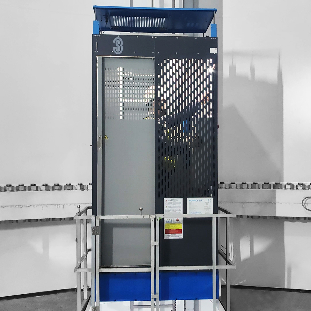
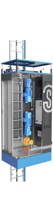
  • Insulated Guide Rail Supply System (optional)
    Adopting the insulated guide rail system, it fundamentally solves the problems of broken skin, breakage and poor cable collection, etc., which is safer.
  • Rack and Pinion Drive
    Pinion drive instead of conventional wire rope makes it operate stably. It avoids the problems of wire rope winding, jamming and breaking of conventional service lift.
  • Dual drive system
    Built-in 2 lifting systems. When one breaks down, the other can still descend and ascend safely under low load.
  • Ready for use during the construction period
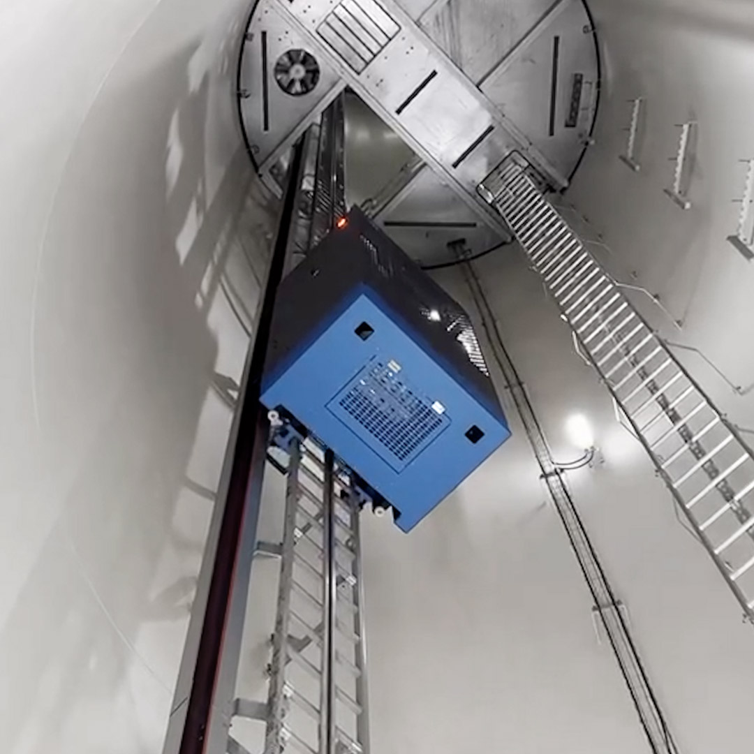
    Once the bottom section of the tower has been installed, Heracles is powered up and ready for use immediately. This lift can be used during the subsequent construction and commissioning phase, increasing the construction’s overall efficiency.
  • Large capacity, large load
    Max load 480 kg, Max capacity 4 persons.  (capacity and load can be customized)
  • Faster speed, higher efficiency
    Max lifting speed of up to 36 m/min, twice as much as conventional lifts.

Product Details

Rack and Pinion Ladder

As the carrier of the lift, the ladder is welded with standard rack and pinion and profiles.

Top Sensing Panel

When the lift comes in contact with an obstacle, the panel is compressed and a sensor is triggered.

Driving device

Ddrive the rack and pinion meshing transmission through the gear motor so that the service lift can descend or ascend towers.

Fall protection system

When the descending speed of the lift exceeds the preset speed of the fall arrester. It will lock automatically and its indicator in the control cabinet will light up to stop the lift.

Control Cabinet

As the control system of the lift, the control cabinet is located inside the car.

Lower Escape Board

Located at the bottom of the lift, it can be opened inside or outside the car for escape or rescue.

Insulated Guide Rail Supply System

It serves as the power supply of the lift, replacing the traditional cable.

Upper Escape Board

Located at the top of the lift, it can be opened inside or outside the car for escape or rescue.

01 / 04

Key Features

  • Comply with GB and CE standards
  • Independent fall protection system
  • Independent escape system
  • Dual drive system
  • Variable frequency drive
  • Overload protection system
  • Insulated guide rail supply system
  • Unpowered descent system

SPECIFICATIONS


Model H480
Rated load 480 kg
Capacity 4 people
Speed 18/36 m/min


Model H350
Rated load 350 kg
Capacity 3 people
Speed 18/36 m/min


Model H240
Rated load 240 kg
Capacity 2 people
Speed 18/36 m/min


Power supply 2.2/4 kW x 2
Dimensions 1200 mm x 860 mm x 2820 mm
Rated voltage 400 V, 50/60 Hz, 3P+PE
Operating temperature -30 ℃ – +60 ℃
(Low temperature type can be customized)


Power supply 1.5/3 kW x 2
Dimensions 1200 mm x 860 mm x 2820 mm
Rated voltage 400 V, 50/60 Hz, 3P+PE
Operating temperature -30 ℃ – +60 ℃
(Low temperature type can be customized)


Power supply 1.5 kW x 2
Dimensions 1030 mm x 750 mm x 2690 mm
Rated voltage 400 V, 50/60 Hz, 3P+PE
Operating temperature -30 ℃ – +60 ℃
(Low temperature type can be customized)
Contact

Get in touch with us now to find out how we
can add value to your operation

Contact us - Americas

This field is for validation purposes and should be left unchanged.

3S Americas, Inc.

Need to order spare parts?
Click here for our spare parts order form.
Order Now